I2c
Jump to navigation
Jump to search
Intro
I ordered a sample MAX7312 from http://maxim-ic.com to begin my adventure into the world of i²c (Inter-Integrated Circuit) communications. I hoping this will allow me to extend the possibilities on future projects as well as current ones.
- Number one rule: Don't take the data sheets for the gospel! At minimum, realize they are prone to errors.
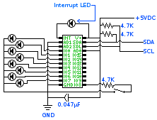
MAX7312 Wiring
- +5VDC to Gumstix's VCC (Pin 30)
- GND to Gumstix's GND (Pin 31)
- SDA to Gumstix's SDA (Pin 19)
- SCL to Gumstix's SCL (Pin 20)
- The capacitor is to filter out noise (keep it as close to V+ as possible)
- The resistors on SDA and SCL are pull up resistors
- AD1 and AD2 are set to ground. AD0 is set to VCC. This sets the address to be 0x42, but that's the 8 bit address. We need the 7 bit address, so we shift it to the left once to get 0x21. Now we have the right address to communicate to the MAX7312 via the gumstix's i2c bus.
- To set port 2 to "input" mode, we execute the following on the gumstix:
./i2c 0x21 wb 0x07 0xFF
- The interrupt LED will turn on when you flip the switch on IO8. It will stay on until we read the MAX7312's i2c bus or until we put the state back. If you read the i2c bus, this will turn the LED off and now when the switch is flipped again, it will turn the interrupt back on. However, if you put the switch back to the way it was before reading, it will also turn off the interrupt. We used the i2c program on the gumstix to read port 2 as such:
./i2c 0x21 rb 0x01
- To set port 1 to "output" mode, we execute the following on the gumstix:
./i2c 0x21 wb 0x06 0x00
- To sequence the LEDs on port 1, do the following on the gumstix:
 ./i2c 0x21 wb 0x02 0x01
 sleep 1
 ./i2c 0x21 wb 0x02 0x03
 sleep 1
 ./i2c 0x21 wb 0x02 0x07
 sleep 1
 ./i2c 0x21 wb 0x02 0x0E
 sleep 1
 ./i2c 0x21 wb 0x02 0x1C
 sleep 1
 ./i2c 0x21 wb 0x02 0x38
 sleep 1
 ./i2c 0x21 wb 0x02 0x70
 sleep 1
 ./i2c 0x21 wb 0x02 0xE0
 sleep 1
 ./i2c 0x21 wb 0x02 0xC0
 sleep 1
 ./i2c 0x21 wb 0x02 0x80
 sleep 1
